Oh baby. Just got my hands on a dozen of these Mitsubishi RD16HHF1s. These are 20W (16W minimum, 19W typical) power devices that can be driven by up to 800 mW. The test circuit given in the PDF shows a 400 mW drive. Darn near any HF QRP kit I have generates 100 mW or more, some of them 250 mW. All we have to do is lash up something and hook up any of these to see what we can get out. QRP is great, but there are so many "deaf" hams these days that I am feeling the urge to add some oomph.
One of the most exciting claims in the documentation is the "no destroy" note for load VSWR tolerance. They list a test condition of 15.2Vdd, Power out as 16W, f=30 MHz, Idq at half an amp into a 50 ohm load on a VSWR of 20:1 (!!!), all phases - "No destroy".
Whoa. Gotta say I love a power amp that can spew 20 watts but doesn't mind if I am hideously mis-matched to the antenna. Talk about forgiving.
More soon! I'll build the test circuit and take some pretty pictures.
Wednesday, January 11, 2017
Monday, February 1, 2016
MSP430G2553 beacon oscillator
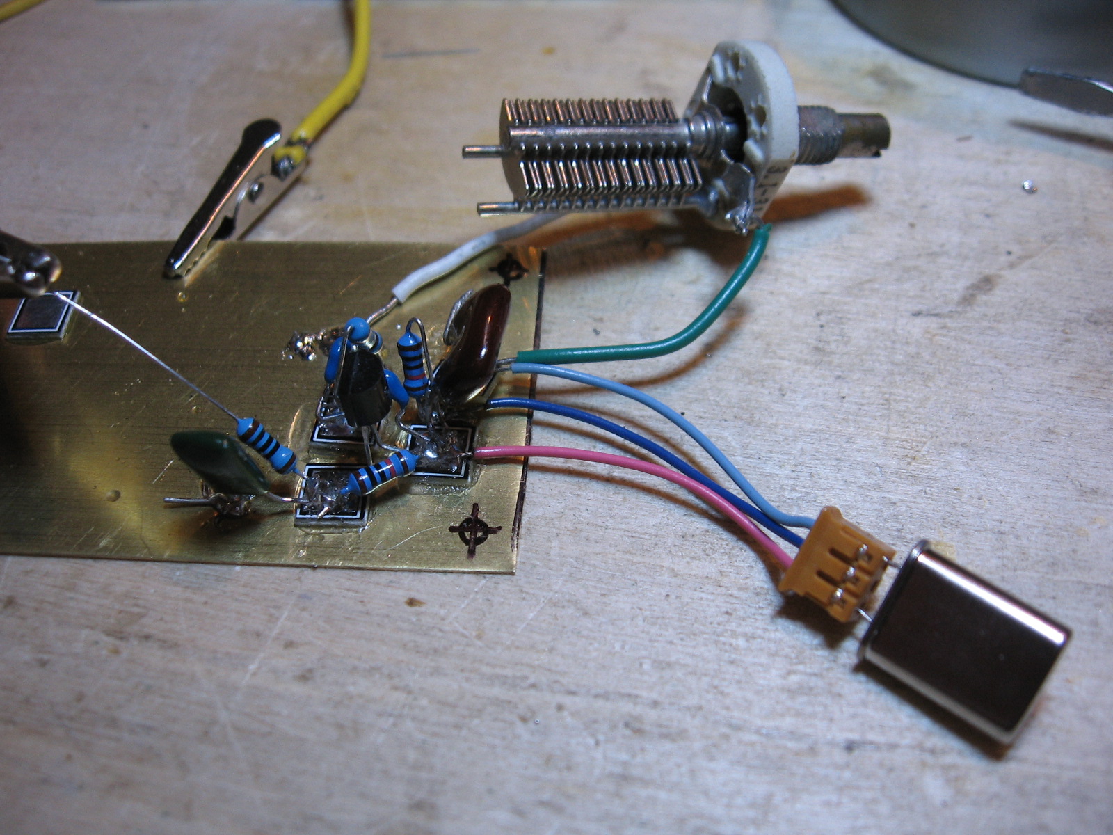
The next step to building the ham beacon is to create an oscillator. I chose a simple Pierce oscillator similar to the ones you find in books. This particular one is in Art of Electronics, Experimental Methods in RF Design, and a dozen or more other publications. The idea is to use two caps to oscillate a transistor using a crystal to set the frequency, with a variable cap between crystal and ground to help "bend" the frequency a bit. There are several features in my circuit that you might find helpful.

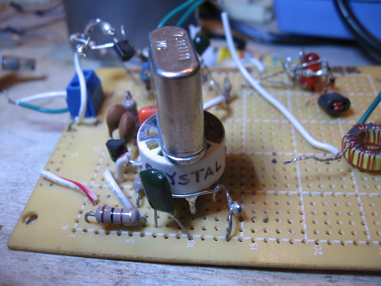
First, notice that I salvaged a 3-wire 0.1 pitch pin socket from some old equipment and I use that for a crystal holder. You can go buy "crystal holders", or use a machine pin socket, or pull something out of the junk pile. I like having the little wires to give my fat fingers enough wiggle room to change crystals easily. At RF frequencies, you have to watch out for lots of long wires, but this little beacon at 7 MHz is not going to suffer from a couple inches of wire.
Another trick I like to use is a solder-style tube socket for the slightly larger, older style crystals. Below is a 9-pin Chinese cheapo socket that I decided was too flimsy to put into a tube circuit. Made a fine crystal holder, though. I soldered half the pins together on one side, and the other half for the other. A Sharpie makes is simple to see how to plug in the crystal. This old perf board had strange imbalances in the oscillator, probably due to the lack of a ground plane. Plastic. Blech. It's in the junk box now.

The beacon circuit is being built on a small scrap of brass plate I bought from K&S Metals (via the local hardware store). Some people swear by copper-clad, but I am offended by the prices. It's just as easy to build small things like this on a simple piece of brass or copper sheet metal. I marked spots for holes later so I can use 6-32 hardware to mount the thing in a project box.
The air variable cap is an antique I got from some eBay deal where an old guy filled a box with junk he had on the bench. Dan's Small Parts has them, too, and probably many others. This one claims to be 3.1 - 31.5 µF, but I measured it to be 3.6 - 35.2. In any case, fully meshed I notice that the voltage developed by the oscillator is about 1.8V peak-to-peak with 11.9VDC as the supply voltage. You don't need one, but I like building circuits with one of these in a strategic spot. For the finished beacon I'll take it out, since I don't really need a variable beacon. Instead, I'll adjust it to value that suits me, measure the result, and replace it with a fixed cap that matches.

As I turn the cap, I can raise the frequency of oscillation from 7.0394 MHz (fully meshed) all the way to 7.044 MHz (no mesh) - a full 5 kHz spread. That's quite nice when you're otherwise rock-bound and need to nudge your frequency a bit. The crystal is labeled 7.040.
Interestingly, as I "bend" the frequency up, the peak voltages go down until I hit 7.044 MHz, where the voltage is about half what we see here. Taking the peak voltage here times .7071, squared, divided by 50 ohms, I get about 8 mW when the cap is fully meshed. The transistor is a 2n3904. That's a pretty strong signal for a 3904. I usually get a result somewhere between 4 mW and 7 mW. [For those of you who like to think in dBm, 8 mW power is around 9 dBm (decibel milliwatts) - for the rest of us, that's 10 raised to the 0.9 power].
The red silver mica cap is the 100 pF isolator that will connect the signal to the next stage, a buffer. I went ahead and put it on there so I can connect the oscilloscope without touching any DC. About half the parts you see are from old equipment I've dismantled for salvage. That little silver mica cap came out of a very old piece of lab equipment that dated from the 50s. I've used it in a half dozen circuits. First thing I ever made with it was a grid-leak for a regenerative receiver.
Another detail you may notice are the little square soldering pads. Those were included in a kit I bought, so I thought I'd give them a try. They are called "MePads". Frankly, I prefer ugly construction, just soldering components together as I go. The little pads are supposed to be glued down, but I already notice them pulling up as I work on the circuit. I intensely dislike circuits that are not rugged, so I probably won't use these again. I'm also suspicious of gimmicky "helper" bits of flotsam that snorkel money away from the active device budget. No offense to those who like these. If you obsess over having "pretty" circuits, maybe they are for you. I care whether it works and couldn't care less how tidy it looks. I found the MePads to be fiddly and not very helpful. They are certainly slower than ugly construction. They aren't even self-adhesive. Not for me. Instead, I'll use high-value resistors as standoffs (1M or higher). We'll see that in the next post, where I will add a buffer to the oscillator, and then the keying circuit.
First, notice that I salvaged a 3-wire 0.1 pitch pin socket from some old equipment and I use that for a crystal holder. You can go buy "crystal holders", or use a machine pin socket, or pull something out of the junk pile. I like having the little wires to give my fat fingers enough wiggle room to change crystals easily. At RF frequencies, you have to watch out for lots of long wires, but this little beacon at 7 MHz is not going to suffer from a couple inches of wire.
Another trick I like to use is a solder-style tube socket for the slightly larger, older style crystals. Below is a 9-pin Chinese cheapo socket that I decided was too flimsy to put into a tube circuit. Made a fine crystal holder, though. I soldered half the pins together on one side, and the other half for the other. A Sharpie makes is simple to see how to plug in the crystal. This old perf board had strange imbalances in the oscillator, probably due to the lack of a ground plane. Plastic. Blech. It's in the junk box now.
The beacon circuit is being built on a small scrap of brass plate I bought from K&S Metals (via the local hardware store). Some people swear by copper-clad, but I am offended by the prices. It's just as easy to build small things like this on a simple piece of brass or copper sheet metal. I marked spots for holes later so I can use 6-32 hardware to mount the thing in a project box.
The air variable cap is an antique I got from some eBay deal where an old guy filled a box with junk he had on the bench. Dan's Small Parts has them, too, and probably many others. This one claims to be 3.1 - 31.5 µF, but I measured it to be 3.6 - 35.2. In any case, fully meshed I notice that the voltage developed by the oscillator is about 1.8V peak-to-peak with 11.9VDC as the supply voltage. You don't need one, but I like building circuits with one of these in a strategic spot. For the finished beacon I'll take it out, since I don't really need a variable beacon. Instead, I'll adjust it to value that suits me, measure the result, and replace it with a fixed cap that matches.

As I turn the cap, I can raise the frequency of oscillation from 7.0394 MHz (fully meshed) all the way to 7.044 MHz (no mesh) - a full 5 kHz spread. That's quite nice when you're otherwise rock-bound and need to nudge your frequency a bit. The crystal is labeled 7.040.
Interestingly, as I "bend" the frequency up, the peak voltages go down until I hit 7.044 MHz, where the voltage is about half what we see here. Taking the peak voltage here times .7071, squared, divided by 50 ohms, I get about 8 mW when the cap is fully meshed. The transistor is a 2n3904. That's a pretty strong signal for a 3904. I usually get a result somewhere between 4 mW and 7 mW. [For those of you who like to think in dBm, 8 mW power is around 9 dBm (decibel milliwatts) - for the rest of us, that's 10 raised to the 0.9 power].
The red silver mica cap is the 100 pF isolator that will connect the signal to the next stage, a buffer. I went ahead and put it on there so I can connect the oscilloscope without touching any DC. About half the parts you see are from old equipment I've dismantled for salvage. That little silver mica cap came out of a very old piece of lab equipment that dated from the 50s. I've used it in a half dozen circuits. First thing I ever made with it was a grid-leak for a regenerative receiver.
Another detail you may notice are the little square soldering pads. Those were included in a kit I bought, so I thought I'd give them a try. They are called "MePads". Frankly, I prefer ugly construction, just soldering components together as I go. The little pads are supposed to be glued down, but I already notice them pulling up as I work on the circuit. I intensely dislike circuits that are not rugged, so I probably won't use these again. I'm also suspicious of gimmicky "helper" bits of flotsam that snorkel money away from the active device budget. No offense to those who like these. If you obsess over having "pretty" circuits, maybe they are for you. I care whether it works and couldn't care less how tidy it looks. I found the MePads to be fiddly and not very helpful. They are certainly slower than ugly construction. They aren't even self-adhesive. Not for me. Instead, I'll use high-value resistors as standoffs (1M or higher). We'll see that in the next post, where I will add a buffer to the oscillator, and then the keying circuit.
Thursday, January 28, 2016
MSP430G2553 beacon
In a former post, I developed a simple beacon code to send my ham call sign KC9TUI to a flashing LED on the Texas Instrument Stellaris development board. It's a great device - but it has a zillion tiny pins. Tiny pins are not practical for the homebrewer. So, I switched over to the MSP430G2553 (a much easier-to-solder 20-pin DIP), loaded the code, and moved it to breadboard. I'm using an LM317 and some caps to select a voltage close to 3.3, and that powers the controller. Notice the 10k resistor which connects pin 1 (Vcc power) to the RST pin 16. This has to be in place or the controller doesn't do a thing. Also, please forgive my, uh, somewhat over-rated caps. I'll get something rated to 16V for the final circuits. These were just the first caps I found. Without them, the noise from the power supply chip can cause havoc with the MSP430. I take that on faith, and have not yet experimented with noisy power sources. The final project powered with batteries will be so quiet that I'm sure it's not an issue.
Here's a quick movie so you can see the LED flashing my call sign, KC9TUI. How's your CW?
See the video on YouTube
The final design will be to draw a PNP emitter to ground. That's a keying circuit I use which I learned in Experimental Methods in RF Design. If you enjoy RF electronics then you just have to have it. The filter design software that comes with it is easily worth the price. I've built that "1st Transmitter" three different times. It's just a great way to start experimenting with RF transmitters.
More on the beacon project when I get it planted inside a watertight project case. The transmitter will run from rechargeables and a solar panel, so there's plenty more work to do before this all gets soldered and mounted.
Here's a quick movie so you can see the LED flashing my call sign, KC9TUI. How's your CW?
The final design will be to draw a PNP emitter to ground. That's a keying circuit I use which I learned in Experimental Methods in RF Design. If you enjoy RF electronics then you just have to have it. The filter design software that comes with it is easily worth the price. I've built that "1st Transmitter" three different times. It's just a great way to start experimenting with RF transmitters.
More on the beacon project when I get it planted inside a watertight project case. The transmitter will run from rechargeables and a solar panel, so there's plenty more work to do before this all gets soldered and mounted.
Saturday, January 23, 2016
MSP430 / Stellaris Beacon program
I like programming the Texas Instrument MSP430 and Stellaris micro-processors. I have several of their kits, one of which is a Stellaris EK-LM4F120XL. Obviously, you have to make sure you set your IDE to your chip type. But I believe this will run OK on most MSP430 and Stellaris boards. I imagine it would be easy to adapt to an Arduino or Raspberry Pi also.
I'm building a small 10mW transmitter with just the oscillator, first buffer, and the keying circuit as shown in "A First Transmitter", Experimental Methods in RF Design (EMRFD). That circuit keys by grounding the base of a PNP transistor. So I developed this to blink an LED, and will later adapt it to also ground an I/O pin.
Here's the code:
/*
Beacon by John Burgoon KC9TUI - January 2016
Blink an LED in Morse code using my callsign
For the EMRFD 1st Transmitter, alternate the emitter pin of the keying transistor to ground instead of (or, perhaps in addition to) flashing an LED.
Hardware Required;
* LaunchPad with an LED
This software is free for public use. Please be certain to change the callsign to your own.
*/
// most launchpads have a red LED
#define LED RED_LED
#define DOTLENGTH 110
#define EL_SPACE DOTLENGTH*1
#define CHAR_SPACE DOTLENGTH*3
#define WORD_SPACE DOTLENGTH*7
String CALL_MSG;
// the setup routine runs once when you press reset;
void setup() {
// initialize the digital pin as an output.
pinMode(LED, OUTPUT);
CALL_MSG = String("BEACON"); // TWO_BY_TWO or BEACON, all else sends "73"
}
// the loop routine runs over and over again forever;
void loop() {
if (CALL_MSG == "TWO_BY_TWO") {
MORSE_C();MORSE_Q();delay(WORD_SPACE);
MORSE_C();MORSE_Q();delay(WORD_SPACE);
MORSE_D();MORSE_E();delay(WORD_SPACE);
MORSE_K();MORSE_C();MORSE_9();MORSE_T();MORSE_U();MORSE_I();delay(WORD_SPACE);
MORSE_K();MORSE_C();MORSE_9();MORSE_T();MORSE_U();MORSE_I();delay(WORD_SPACE);
MORSE_K();delay(WORD_SPACE);
} else if (CALL_MSG == "BEACON") {
MORSE_K();MORSE_C();MORSE_9();MORSE_T();MORSE_U();MORSE_I();delay(WORD_SPACE);TONE();delay(WORD_SPACE);
} else {
MORSE_73();delay(WORD_SPACE);
}
}
void DASH() {
digitalWrite(LED, HIGH); // turn the LED on (HIGH is the voltage level)
delay(CHAR_SPACE); // wait for a dash-length of time
digitalWrite(LED, LOW); // turn the LED off by making the voltage LOW
delay(EL_SPACE); // wait for a dit-length of time
}
void DIT() {
digitalWrite(LED, HIGH); // turn the LED on (HIGH is the voltage level)
delay(EL_SPACE); // wait for a dit-length of time
digitalWrite(LED, LOW); // turn the LED off by making the voltage LOW
delay(EL_SPACE); // wait for a dit-length of time
}
void TONE() {
digitalWrite(LED, HIGH);
delay(WORD_SPACE*2);
digitalWrite(LED, LOW);
delay(EL_SPACE);
}
void MORSE_K() {
DASH(); DIT(); DASH();delay(CHAR_SPACE);
}
void MORSE_C() {
DASH();DIT();DASH();DIT();delay(CHAR_SPACE);
}
void MORSE_9() {
DASH();DASH();DASH();DASH();DIT();delay(CHAR_SPACE);
}
void MORSE_T() {
DASH();delay(CHAR_SPACE);
}
void MORSE_U() {
DIT();DIT();DASH();delay(CHAR_SPACE);
}
void MORSE_I() {
DIT();DIT();delay(CHAR_SPACE);
}
void MORSE_Q() {
DASH();DASH();DIT();DASH();delay(CHAR_SPACE);
}
void MORSE_D() {
DASH();DIT();DIT();delay(CHAR_SPACE);
}
void MORSE_E() {
DIT();delay(CHAR_SPACE);
}
void MORSE_73() {
DASH();DASH();DIT();DIT();DIT();delay(EL_SPACE);DIT();DIT();DIT();DASH();DASH();delay(WORD_SPACE);
}
Thursday, January 21, 2016
HW-8 IF transformer replacement
My cousin, Elmer, and lifelong pal KR3EP did some good old-fashioned horse-trading and, in the bargain, got his hands on a Heathkit HW-8. He was kind enough to give it to me, so I started using it. I instantly decided this was one of the perfect radios for me. It's not too fancy, but it performs quite well. It's one of the most-modified of radios, too, which means a lot is written about it.
 |
| This ad image was swiped from the web. I'm old enough to recall the ad. |
However, even though many people declare what they've done, very few show pics and explain the process. So, when I realized that the 40m band had no signal at all, I decided to repair it and post the progress here.
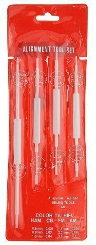
This radio has excellent documentation online. Google it up. After some initial testing, I found that the 15.895 MHz crystal was getting the right voltage, yet was not oscillating.This crystal is mixed to produce the 7 - 7.250 MHz bandwidth when the "7 MHz" switch is pressed. The diodes seemed OK, so I decided to follow the alignment procedure. If you do this, OBTAIN THE CORRECT "twiddle" stick - a.k.a an "alignment tool". You heard me. USE THE RIGHT TOOL. If one of your hands sneaks over and grabs a hex key, cut off that hand and put it, along with the hex key, in the trash. DO NOT USE A METAL HEX KEY. THIS MEANS YOU.
The little nylon hex adjustment tools are available to purchase on the Web, and if you want to fool with radios you really should have a set. I purchased mine from eBay - the "Universal Color TV Alignment Tool Set - ST-13". The seller shipped right away, so I had it in a jiffy.

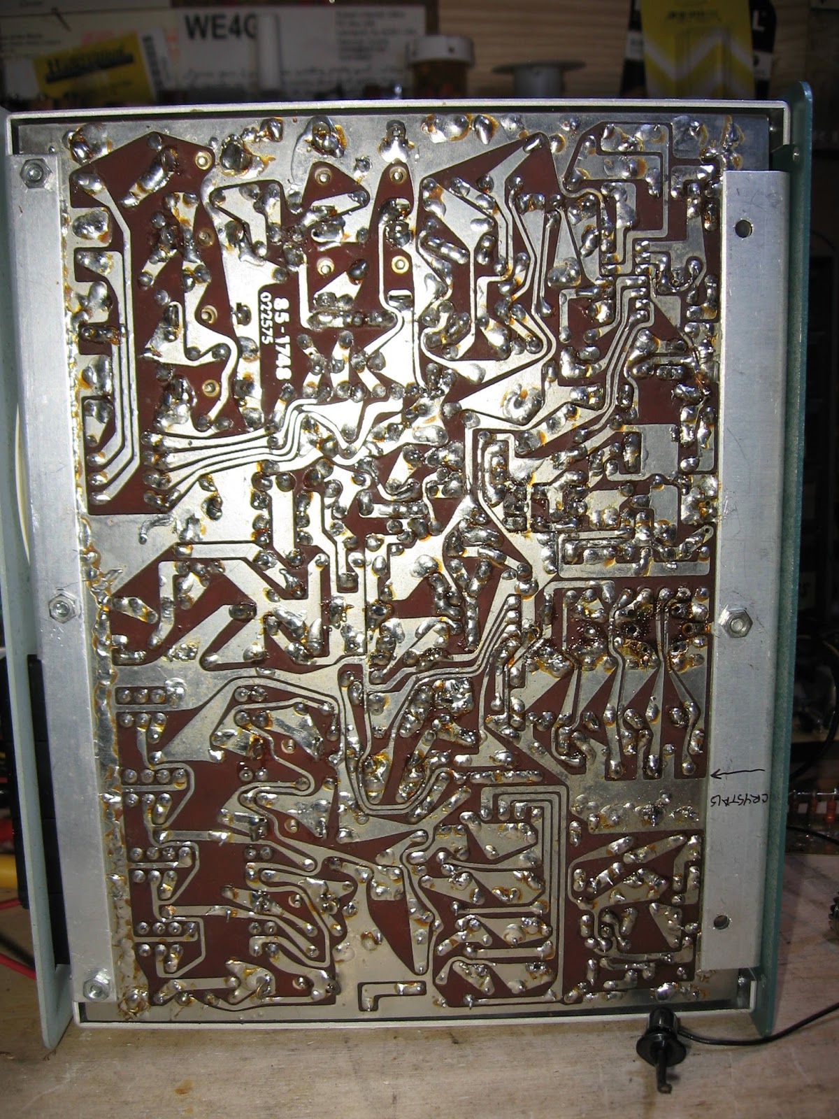
Some gomer in years past ignored this, and crushed the upper slug used to tune the 40m band. It was stuck fast in the little cardboard tube and wouldn't budge. So, I de-soldered it from the unit, along with its little metal shield. The spot it came from is midway down the left edge. There are actually six holes, since there are two for the lower slug wires and two for the upper slug wires and two for the shield.
 |
| The IF transformer is just a pair of wires on a cardboard form, with two adjustable ferrite slugs inside. |
Also, you'll notice that I marked the "front" of the can and noted the way the slug-tuned inductor aligns with the board. (The inductor has a mark also, hard to see). It will save me having to figure it out from the schematic when I replace it. If you look closely, you'll notice someone (probably the same person) slightly crushed the IF shield canister with a pair of pliers. Doofus. I'll call him "Ralph". Don't be like Ralph. If you want to use a hex key on a slug-tuned inductor or transformer, DON'T. And if you crush the slug and decide to remove the shield from any old radio, de-solder the shield from the back side using a little solder braid. DON'T CRUSH IT WITH PLIERS, IT WON'T COME OUT THAT WAY, RALPH. Look closely at this picture, next to the hex nut mid-way down the right side of the frame, and you can see the hole where the IF transformer goes.
 |
| The holes look burnt, but actually that's just old solder flux. I'll clean it off later. |
I contacted Earl Andrews up in Canada, who may be able to repair or maybe replace the transformer. However, while I wait to see if I can restore the original part, I thought I'd experiment a little. Calculations show that the lower inductor coil should measure somewhere in the range of 1.4 µH. I measured this with my trusty LCR meter and found it to measure 1.390. The lower slug was aligned to maximum voltage before I removed it, so that feels spot on. The upper coil should be somewhere in the 0.771 µH range, but when I measured it I found 0.766. So it's no wonder that the 40m crystal did not oscillate.
Thing is, we can go ahead and wind two inductors on toroid cores and solder them in just to see if we can get the radio working while we wait on the original inductor to be repaired. So I'll do that and post the results here in a new entry.
Thing is, we can go ahead and wind two inductors on toroid cores and solder them in just to see if we can get the radio working while we wait on the original inductor to be repaired. So I'll do that and post the results here in a new entry.
LCR meter
The very first electronic measurement instrument I owned was a digital voltmeter. Not long after that, I obtained a 15MHz oscilloscope. But if I had it to do over again, I'd purchase a decent LCR meter.
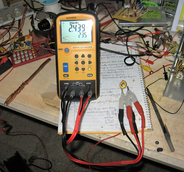
I bought this Escitec VA520 at the 2015 Dayton Hamfest. I have lost the business card of the gentleman who sold it to me; if I still had it, I'd send him a thank you note. I can sit down to the bench and measure inductance with reasonable accuracy - something that is vital to understanding circuits. One can often figure out a capacitance or a resistance, but to have a meter that gives me a quick, reasonably accurate L, and a Q at 1 - 100 kHz - well, that has added to my understanding of circuits by leaps and bounds. I've never tried the USB connection yet, but when I sit down to characterize a batch of crystals for filtering I'll give it a whirl and report back here.
It's fairly simple to build one's own inductance meter, and I did so. It's neat to build the circuit, test it against an industrial instrument, and realize one is within 2% of spec. And lately I'm learning to program Nokia 5110s with MSP430 processors from Texas Instruments. So I'll end up with a home brew L-meter with digital readout to sit next to this handsome VA250.
But here's the main point: if I had had a meter in my early days, I would have spent a LOT less time trying to figure out what I had in the scrap bin, and a LOT more time building things with what I had.
The most fun thing (next to measuring my way through an old cigar box full of RF chokes and Philco inductors from old radios) has been to wind a transformer on a core and then watch the measurement change as I adjust the wires. It's fairly simple to rig up a known cap on a breadboard, attach the result, measure the resulting resonant frequency, and confirm the meter readings. It's certainly good enough for the kind of hobby work I do. Once I get that close, I can fine tune a toroidal inductor or transformer by moving the wires around. But it's a real time-saver to measure before I solder, know I'm close, and fine tune later once everything else is in place.
Tuesday, March 3, 2015
Power out on the 17m Rockmite
I made the power and efficiency mods on my 17m Rockmite build. I gently, oh so gently, crushed the living daylights out of the ferrite toroid provided. Woops. So, undaunted, I substituted a T37-2 toroid. Now this turns ratio of 8:3 in a ferrite with AL = 150 is obviously going to yield far more power transfer than the same winding using the #2 material with AL =, uh, 5. What was I thinking? I was thinking I wanted to get out there, just get out there, even if it was going to be with 9 femptowatts. It's usual for me to go ahead and try things, rather than wait on mail order or rip the guts out of something that is already working. Nope, I don't kill off old builds to power new ones. Lots of years in college so I could afford to buy myself some parts. And once something is working, I'm darned if I'm gonna be the one to break it...
What is interesting here is the measured power out. Substituting a toroid with 1/30th as much AL seemed like to me to be asking for 1/30th the power. But, lo and behold, I measured 0.98V peak to peak using my RF probe, and confirmed it in my B&K 15MHz oscilloscope, pretty much looked like 1 volt PTP. Then I did the power calculation for the RF probe measured voltage, remembering to add in the 0.25V for the diode, and arrived at 68 milliwatts. Wow! I have to admit I was surprised.
The ferrites are on order, but it leaves me wondering about the difference in output power. I'll sit down and hit the books and follow up this post with some theory about how that happened.
Subscribe to:
Posts (Atom)